연구논문

Control Moment Gyroscope Torque Measurements Using a Kistler Table for Microsatellite Applications

Goo-Hwan Shin1,https://orcid.org/0000-0002-7712-2511, Hyosang Yoon1https://orcid.org/0000-0002-9163-4812, Hyeongcheol Kim1https://orcid.org/0009-0003-4884-8721, Dong-Soo Choi2https://orcid.org/0009-0007-8195-5130, Jae-Suk Lee2https://orcid.org/0009-0001-9717-9777, Yeong-Ho Shin2https://orcid.org/0009-0007-6995-4872, EunJi Lee3https://orcid.org/0000-0002-7159-3881, Sang-sub Park3https://orcid.org/0009-0002-0633-6501, Seokju Kang3https://orcid.org/0000-0001-6660-8754
Author Information & Copyright
1Korea Advanced Institute of Science and Technology, Daejeon 34141, Korea
2Justek Incorporated, Pyeongtaek 17711, Korea
3Hanwha Systems, Yongin 17121, Korea
Corresponding author : Goo-Hwan Shin, Tel : +82-42-350-8622, E-mail : goohshin@kaist.ac.kr

© Copyright 2024 The Korean Space Science Society. This is an Open-Access article distributed under the terms of the Creative Commons Attribution Non-Commercial License (http://creativecommons.org/licenses/by-nc/4.0/) which permits unrestricted non-commercial use, distribution, and reproduction in any medium, provided the original work is properly cited.

Received: Jan 19, 2024; Revised: Feb 08, 2024; Accepted: Feb 13, 2024

Published Online: Feb 29, 2024

Abstract

Attitude control of a satellite is very important to ensure proper for mission performance. Satellites launched in the past had simple missions. However, recently, with the advancement of technology, the tasks to be performed have become more complex. One example relies on a new technology that allows satellites quickly alter their attitude while orbiting in space. Currently, one of the most widely used technologies for satellite attitude control is the reaction wheel. However, the amount of torque generated by reaction wheels is too low to facilitate quick maneuvers by the satellite. One way to overcome this is to implement posture control logic using a control moment gyroscope (CMG). Various types of CMGs have been applied to space systems, and CMGs are currently mounted on large-scale satellites. However, although technological advancements have continued, the market for CMGs applicable to, small satellites remains in its early stages. An ultra-small CMG was developed for use with small satellites weighing less than 200 kg. The ultra-small CMG measured its target performance outcomes using a precision torque-measuring device. The target performance of the CMG, at 800 mNm, was set through an analysis. The final torque of the CMG produced through the design after the analysis was 821mNm, meaning that a target tolerance level of 10% was achieved.

Keywords: control moment gyroscope; agile attitude control; Kistler table; torque; reaction wheel; maneuver

1. INTRODUCTION

Advances in semiconductor technology have accelerated the development of satellite technologies. Even just 20 years ago, performance outcomes such as the resolution compared to the size of a satellite were not efficient. In other words, the resolution of an earth observation satellite could be increased by increasing the size of the optical system aperture. However, with recent advances in electrical and electronic technologies, hardware and software technologies have been developed such that it is now possible to increase the resolution while reducing the size of the optical system aperture. With regard to the scale of satellites, their size and volume have become significantly smaller. However, despite the improvements in performance capabilities, there has not been much change in terms of usability. As one example, it is important for Earth observation satellites to secure a large amount of imagery but to maintain a small quantity. Earth observation satellites are now required to have more rapid rotational maneuverability and other abilities than compared to those in the past. These satellites, known as agile satellites, require attitude control systems that can provide rapid multi-targeting pointing and tracking capabilities. An agile satellite is much more efficient and functional, and data return of substantially increased by given agility [1]. In particular, when considering uses such as surveillance and reconnaissance, securing video in real time is paramount. Currently, images using optical cameras mounted on Earth observation satellites capture target points after an appropriate attitude control step. Attitude control of Earth observation satellites uses a reaction wheel assembly (RWA). The existing RWA is an essential driving device for attitude control of satellites. From ultra-small cube satellites to very large geostationary satellites, the RWA is an essential driving device. However, it has a simple operating structure and the driving torque generated during rotation is low [2]. In other words, the force required for attitude maneuvering the satellite is low, meaning that quick maneuvering is hindered. With low driving torque, there is no torque for quick maneuvers to the left or right based on the satellite’s flight direction. On the other hand, when a spin motor rotating at a high speed is rotated around a gimbal axis, very large torque or momentum is generated. A CMG is a device that generates a large amount of torque using a gimbal. When a CMG is mounted on a satellite and three-axis attitude control is utilized, both the normal operation mode and a rapid operation mode are possible. Future satellite applications, such as missile-targeting, imaging and the tracking of ground moving targets will, as a necessity, require the ability to execute rapid rotational maneuvers. For instance, for the next generation of commercial earth imaging satellites, it is preferred to move the entire spacecraft body rapidly compared to than to sweeping only the imaging system from side to side. This ensures improved stability and high resolution images with better definition [1,3-11]. Therefore, in this study, we present torque measurement results from the development of an 800 mNm class CMG that can be mounted on a microsatellite, for which demand is rapidly increasing.

2. CMG HW SPECIFICATIONS AND CONFIGURATION

The performance goals of the CMG that can be mounted on a microsatellites are shown in Table 1 [2]. Table 1 establishes the specifications of the weight, volume, and communication and power for the interface. In addition, the torque value required for highly agile attitude control of the microsatellite is set to 800 mNm as the target specification when rotating the gimbal at the maximum rotation speed.

Table 1. CMG target specifications
Items Specifications
Torque 800 mNm
Dimensions 106 mm × 106 mm × 158 mm
Mass 3.5 kg
Communications RS422
Voltage +28 V
Power consumption (standby/peak) 6 W/26 W
Download Excel Table

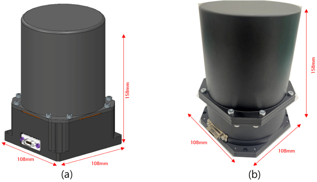
Considering the values in Table 1, where the CMG development target specifications are established, the CMG produced based on these is shown in Fig. 1. The CMG, which is size is 106 mm × 106 mm × 158 mm in size, and weighs 3.5 kg, was developed to be suitable for high-mobility attitude control of microsatellites [2].
jsta-4-1-12-g1
Fig. 1. External configuration of a CMG: (a) CAD modeling and configuration, and (b) CMG H/W manufacturing configuration.
Download Original Figure

3. CMG HW PERFORMANCE TEST

3.1 CMG Axis-Alignment for Torque Measurement

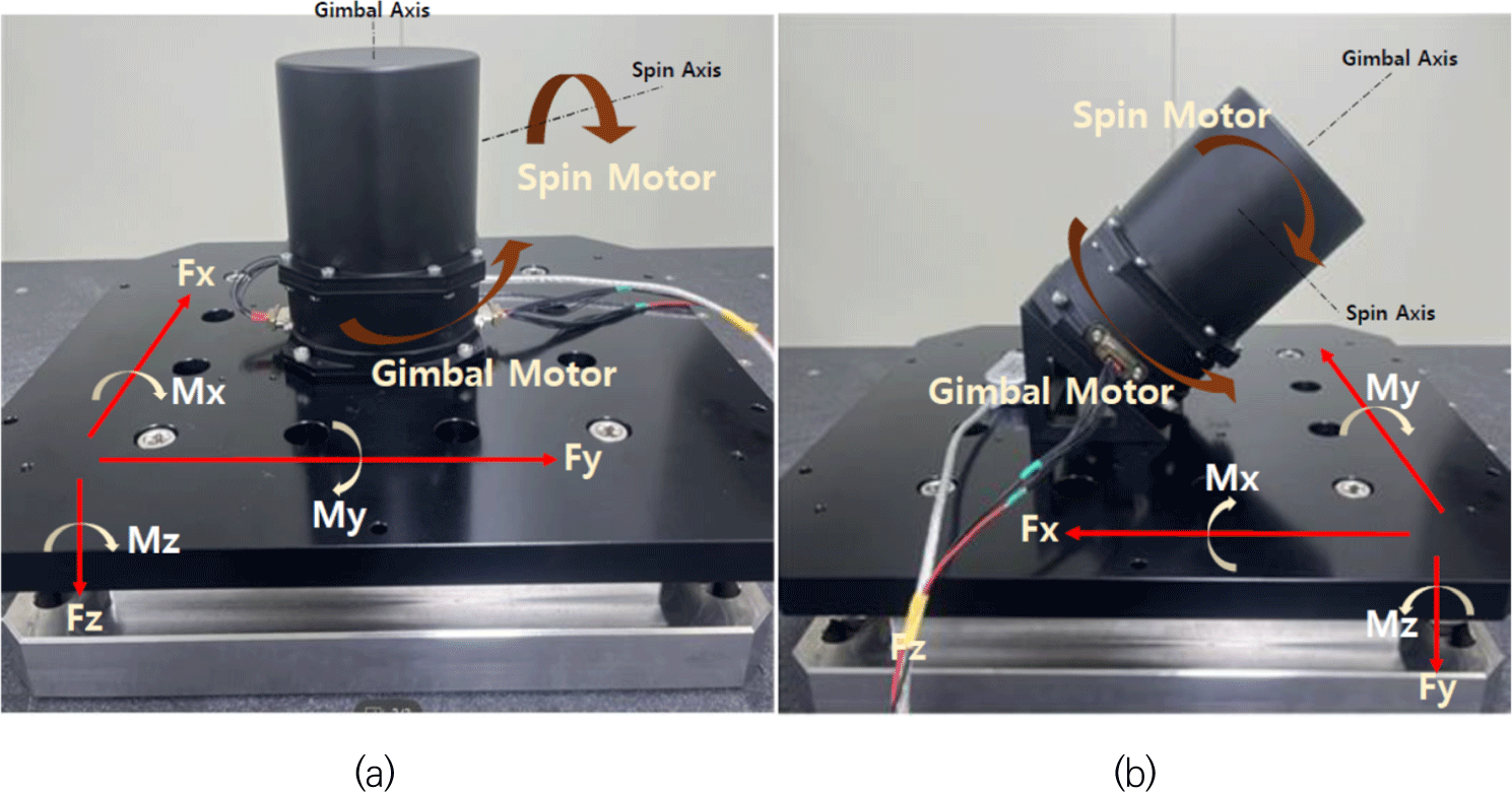
There are various ways to measure CMG performance capabilities. Considering these various methods, in this study, performance was measured using a Kistler Table, which is one of the most commonly used methods for measuring the torque of a rotary motors. Fig. 2 shows the shape of the Kistler Table, which is installed on the granite. A granite plate was built to minimize the effects of vibration and other effects when the CMG rotates at a high speed. The CMG was then assembled on the Kistler Table, and the coordinate axes were defined as shown in Fig. 2 to measure the torque generated from the CMG for each axis.
jsta-4-1-12-g2
Fig. 2. Stone surface table, CMG assembly, and axis definitions: (a) Installed at a 90-angle with the Kistler table on stone, and (b) Installed at a 45-angle with the Kistler table, the torque directions of each axis Fx, Fy, and Fz are also shown.
Download Original Figure

As shown in Fig. 2(a), the CMG was placed in the center on the granite. By locating the CMG at the center of the Kistler Table, the intent is to secure the error between the theoretical values and the actual measured values. Fig. 2(b) shows the assembly shape used to measure the generated torque value, assuming that it is mounted on the actual satellite structure. In the future, individual CMGs will be clustered considering various shapes and should be arranged to generate high mobility torque on the axes required in various shapes depending on the mission.

3.2 CMG Torque Test Configuration

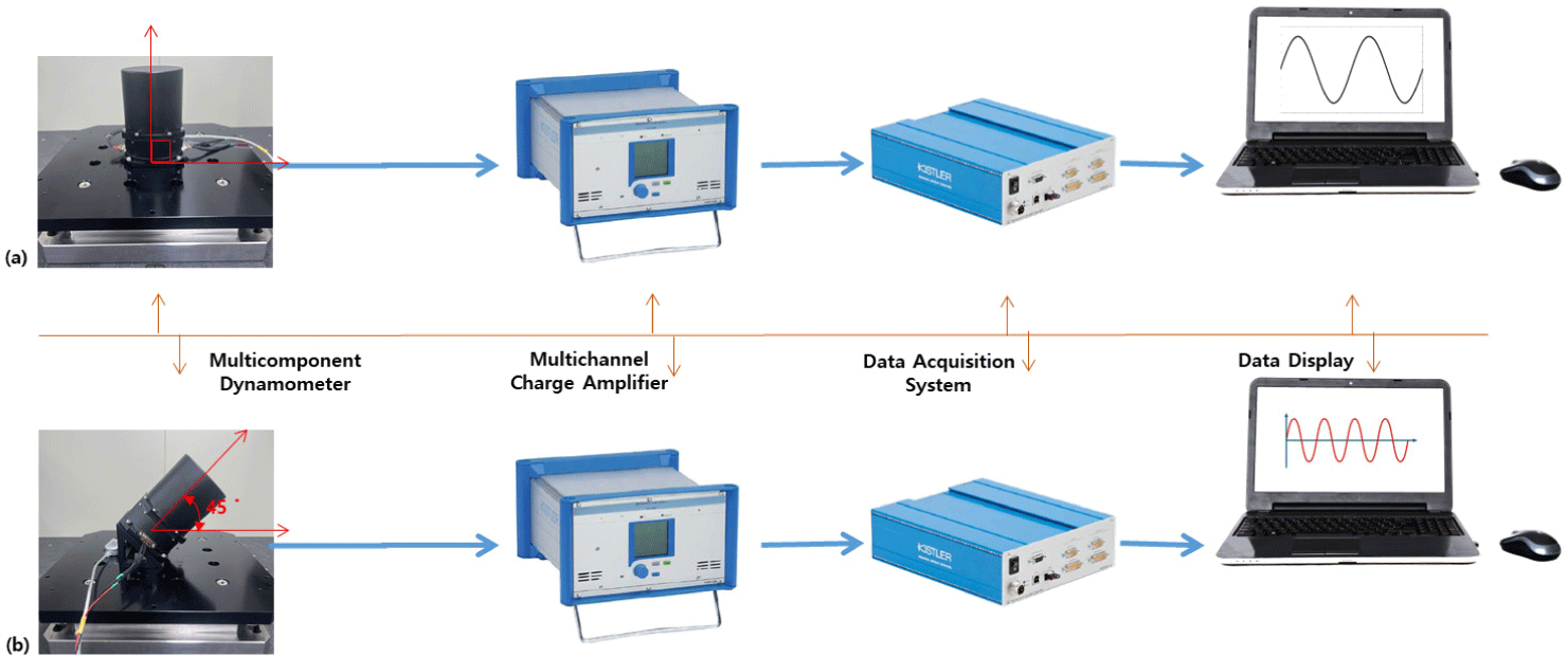
The interface between the Kistler Table and the surrounding sensor for measuring the CMG torque is shown in Fig. 3 below. The CMG is assembled on the stone surface table, and the Kistler Table is positioned at the bottom. A three-axis accelerometer is installed at the bottom of the CMG. Acceleration information generated during the operation of the CMG is output from the Kistler Table, the output signal is input to a DAQ channel, a signal acquisition device, through an amplifier and stored in the control computer.
jsta-4-1-12-g3
Fig. 3. Kistler Table configuration and sensor interface for CMG torque measurement: (a) Kistler Table and 90° angle measurement interface, and (b) CMG measurement interface assembled at a 45° angle considering actual missions.
Download Original Figure

The main components for measuring the CMG torque consist of the Kistler Table, Signal Amplifier, DAQ system, control computer. The main specifications are as follows:

  • - Kistler Table: System with built-in piezoelectric three-component dynamometer

  • - Signal Amplifier: Signal charge and amplification system

  • - DAQ system: Moment calculation for each of the three axes Fx, Fy, Fx in eight channels of the Kistler table’s four piezoelectric three-component dynamometers

  • - Notebook: Displays the measured torque

4. TEST RESULTS AND DISCUSSION

The configuration and axis definition for CMG torque measurement were established in the previous chapter. Based on this, this chapter describes the torque measurement results for the CMG assembly configuration.

4.1 CMG Torque Test Results Mounted at 90° Angle

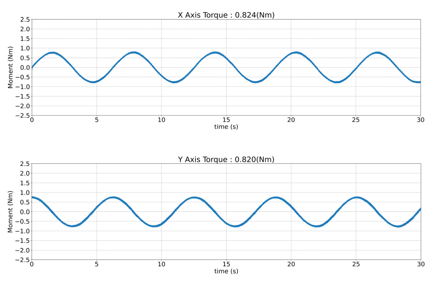
The CMG torque measurement results in a shape assembled at right angles (CMG is assembled vertically with the Kistler table) to the Kistler Table are as follows. When measuring the torque of the CMG, the torque was measured by varying the speed of the spin motor by considering additional operating conditions depending on the nominal conditions and mission. The error with the simulation was also checked (Fig. 4).
jsta-4-1-12-g4
Fig. 4. CMG torque measurement results under nominal measurement conditions, where the spin operates at 5,000 rpm and the gimbal motor rotation angular speed is 1°/s.
Download Original Figure

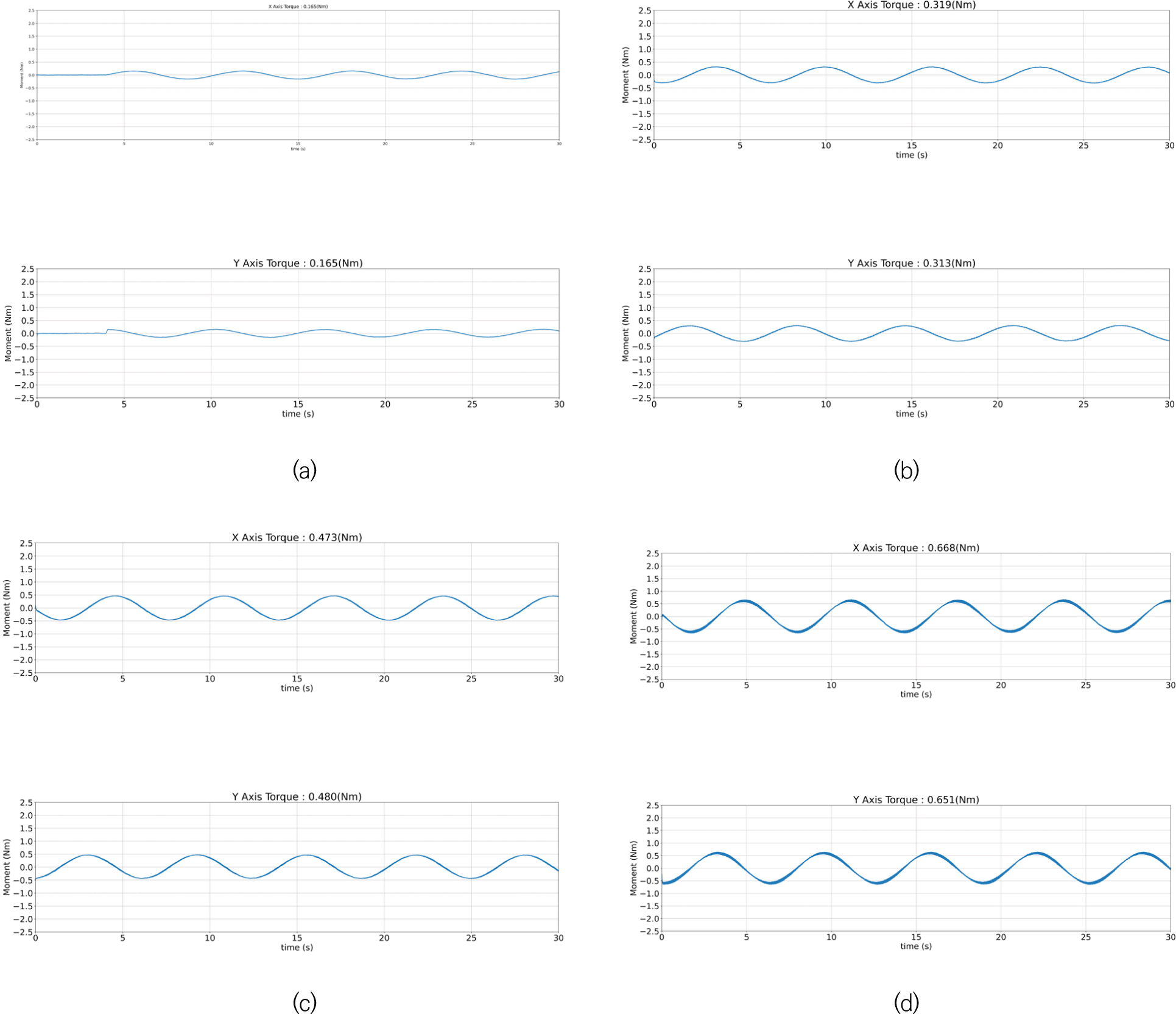
Fig. 5 below shows the speed of the spin motor starting at 1,000 rpm and changing up to 5,000 rpm.
jsta-4-1-12-g5
Fig. 5. CMG torque measurement results at a right angle: (a) CMG torque measurement results under nominal measurement conditions, where the spin operates at 1,000 rpm and the gimbal motor rotation angular speed is 1°/s, (b) CMG torque measurement results under nominal measurement conditions, where the spin operates at 2,000 rpm and the gimbal motor rotation angular speed is 1°/s, (c) CMG torque measurement results under nominal measurement conditions, where the spin operates at 3,000 rpm and the gimbal motor rotation angular speed is 1°/s, and (d) CMG torque measurement results under nominal measurement conditions, where the spin operates at 5,000 rpm and the gimbal motor rotation angular speed is 1°/s.
Download Original Figure
4.2 CMG Torque Test Results Mounted at 45° Angle

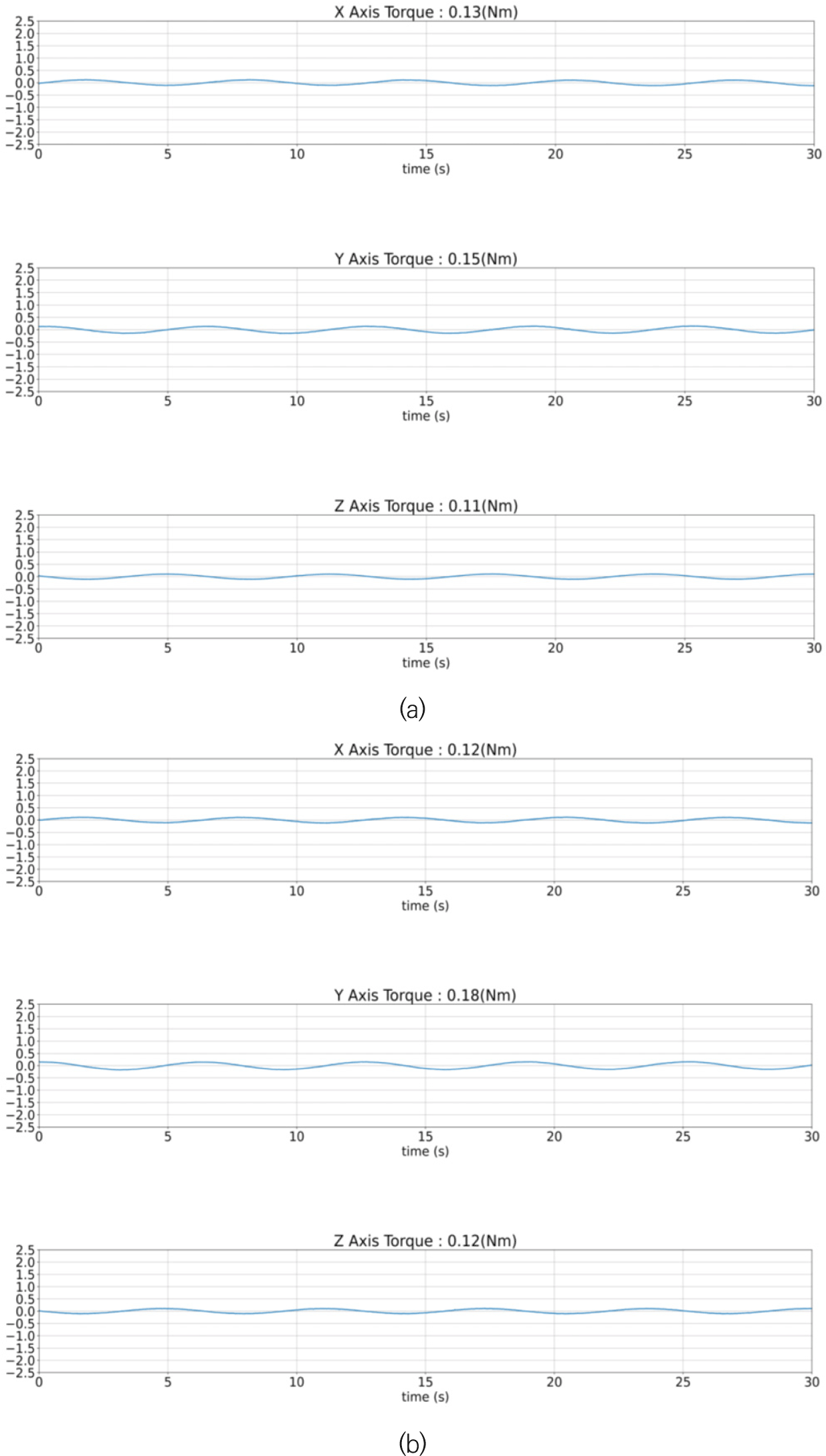
The CMG torque measurement results for the shape assembled at a 45° angle on the Kistler Table are as follows. The performance verification was completed based on nominal conditions when measuring the CMG torque. The Kistler Table and the CMG torque tilted at a 45° angle are a CMG mounting configuration that takes into account the actual mission environment. In this test, considering the operating conditions, the speed of the spin motor was varied from 1,000 rpm to 4,000 rpm and the torque that can be generated by CMG was measured. Fig. 6 below shows the torque generated after setting the speed of the spin motor built into the CMG to 1,000 rpm.
jsta-4-1-12-g6
Fig. 6. CMG torque measurement results tilted at a 45° angle: (a) Kistler Table-Spin motor center matching (with the spin motor operating at 1,000 rpm and a gimbal motor rotation angular speed of 1 rad/s), and (b) Kistler Table-Gimbal motor center matching (1,000 rpm for the spin motor and 1 rad/s rotational angular speed for the gimbal motor).
Download Original Figure

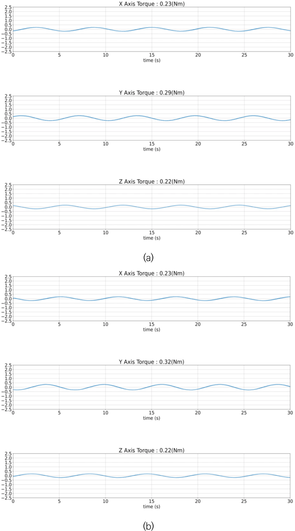
Fig. 7 shows the torque generated after setting the speed of the spin motor built into the CMG to 2,000 rpm. It can be seen that the generated torque increases by approximately 178% compared to that in Fig. 6. This shows that the speed of the CMG spin motor is related to the amount of torque generated.
jsta-4-1-12-g7
Fig. 7. CMG torque measurement results tilted at a 45° angle: (a) Kistler Table-Spin motor center matching (with the spin motor operates at 2,000 rpm and the gimbal motor rotation angular speed is 1 rad/s), and (b) Kistler Table-Gimbal motor center matching (2,000 rpm for the spin motor and 1 rad/s rotational angular speed for the gimbal motor).
Download Original Figure

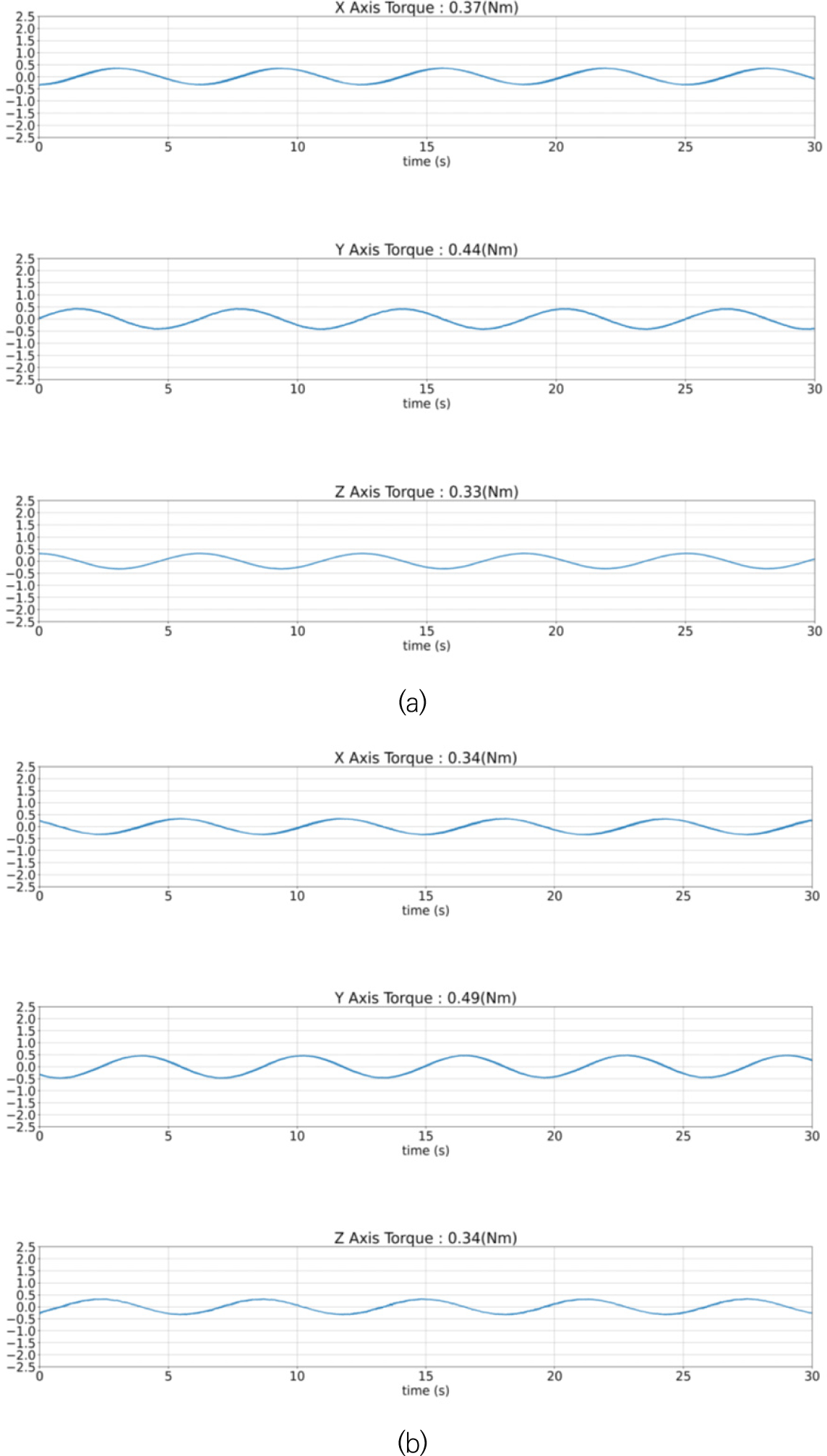
Fig. 8 below shows the torque generated after setting the speed of the spin motor built into the CMG to 3,000 rpm. This figure shows that the generated torque increases by about 168% compared to that in Fig. 7, including that the speed of the CMG spin motor is related to the amount of torque generated.
jsta-4-1-12-g8
Fig. 8. CMG torque measurement results tilted at a 45° angle: (a) Kistler Table-Spin motor center matching (with the spin motor operates at 3,000 rpm and gimbal motor rotation angular speed is 1 rad/s), and (b) Kistler Table-Gimbal motor center matching (spin motor operating at 3,000 rpm and gimbal motor’ rotational angular speed of 1 rad/s).
Download Original Figure

Fig. 9 shows the torque generated after setting the speed of the spin motor built into the CMG to 4,000 rpm. In this case, the generated torque increases by about 157% compared to that in Fig. 8. As above, the speed of the CMG spin motor is related to the amount of torque generated.
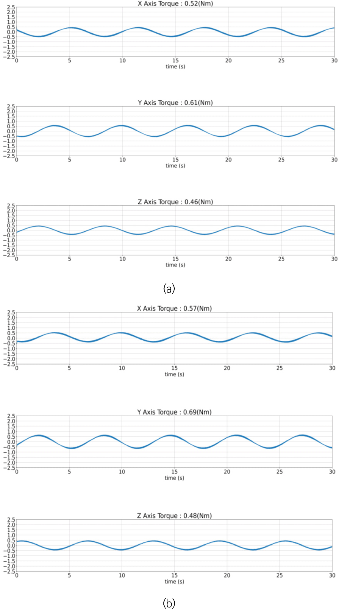
jsta-4-1-12-g9
Fig. 9. CMG torque measurement results tilted at a 45° angle: (a) Kistler Table-Spin motor center matching (with the spin motor operating at 4,000 rpm and the gimbal motor rotation angular speed is 1 rad/s), and (b) Kistler Table-Gimbal motor center matching (spin motor operating at 4,000 rpm and gimbal motor’ rotational angular speed of 1 rad/s).
Download Original Figure

Lastly, the torque generated when the spin motor speed is set to 5,000 rpm in a shape assembled by tilting the angle of the Kistler Table and CMG by 45° is shown in Fig. 10. Fig. 10 below shows the change in the torque on the time axis after setting the speed of the spin motor built into the CMG to 5,000 rpm. Here, the generated torque increases by approximately 117% compared to the previous Fig. 9 indicating that the speed of the CMG spin motor is related to the amount of torque generated.
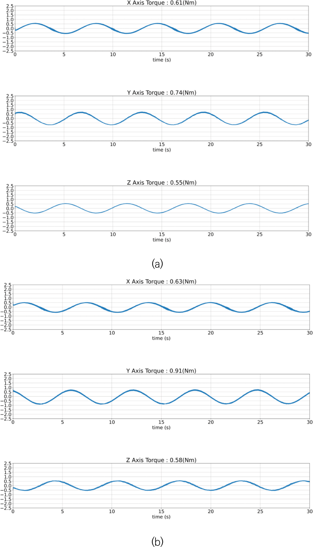
jsta-4-1-12-g10
Fig. 10. CMG torque measurement results tilted at a 45° angle: (a) Kistler Table-Spin motor center matching (with the spin motor operating at 5,000 rpm and the rotation angular speed of gimbal motor is 1 rad/s), and (b) Kistler Table-Gimbal motor center matching (spin motor operating at 5,000 rpm and with a gimbal motor’ rotational angular speed of 1 rad/s).
Download Original Figure
4.3 CMG Power Consumption

The power consumption of CMG was measured in two modes. One was measured in stand-by mode and the other was measured when the spin motor’s rotational speed was at maximum. The results of the CMG power consumption are as follows (Table 2).

Table 2. CMG power consumption
Mode Test results
Stand-by power 1.40 W
Peak power at 5,000 rpm 9.24 W
Download Excel Table

5. CONCLUSION

The torque was measured when the CMG was tilted at a 45° angle, taking into account a vertically fastened condition and a clustered condition. When the CMG was vertically fastened, measurements were taken by fastening the CMG to the center of the Kistler Table. Under the condition of fastening the CMG at an angle of 45°, the torque was measured when the center of the CMG’s spin motor was at the center of the Kistler Table and when the center of the gimbal motor was at the center of the Kistler Table. Comprehensive test results of the torque generated according to the assembly angle of this CMG are summarized below. When the CMG was fastened vertically, it was found that the measured torque increased proportionally when driven in stages from 1,000 rpm to 4,000 rpm compared to the nominal condition of 5,000 rpm. Table 3 summarizes the generated torque.

Table 3. Torque for each axis of the CMG assembled at a right angle
Spin motor’s rotational speed [rpm] Gimbal motor’s rotational speed [rad/s] CMG torque (mounted at a right angle)
Mx (mNm) My (mNm) Mz (mNm) Estimated torque (mNm) Measured torque (mNm)
1,000 1 164 165 0.01 164 164
2,000 318 313 0.02 328 316
3,000 473 480 0.04 492 476
4,000 668 651 0.08 657 659
5,000 824 820 0.06 821 821
Download Excel Table
Table 4. Torque for each axis of the CMG assembled at a 45° angle
Spin motor’s rotational speed [rpm] Gimbal motor’s rotational speed [rad/s] CMG torque (Kistler Table-Spin motor center matching) CMG torque (Kistler Table-Gimbal motor center matching)
Mx (mNm) My (mNm) Mz (mNm) Mx (mNm) My (mNm) Mz (mNm)
1,000 1 128 153 114 121 181 117
2,000 234 294 217 234 322 222
3,000 369 439 328 342 487 336
4,000 521 606 459 574 691 478
5,000 608 738 552 629 911 581
Download Excel Table

The torque generated by the CMG when the gimbal motor is tilted at 45° is shown in Table 3 below. It was found that as the CMG was tilted by 45°, the moment in the X and Y directions became smaller and the moment in the Z direction became larger compared to those when the CMG shape was assembled at 90°. It was found that the measured torque increases proportionally when driven in stages from 1,000 rpm to 4,000 rpm compared to the nominal condition of 5,000 rpm.

ACKNOWLEDGMENTS

This work was supported by the program of the CMG-based Small Satellite Agile Attitude Control Technology funded by the Hanwha Systems of Korea.

References

1.

Berner R, Control moment gyro actuator for small satellite applications, PhD Dissertation, University of Stellenbosch (2005).

2.

Shin GH, Yoon H, Kim H, Choi DS, Lee JS, et al., Highly agile actuator development status of an 800 mNm control moment gyro (CMG), J. Space Technol. Appl. 3, 322-332 (2023).

3.

Rhee SW, Kwon HJ, Low cost small CMG performance test and analysis, J. Korean Soc. Aeronaut. Space Sci. 39, 543-552 (2011).

4.

Defendini A, Lagadec K, Guay P, Blais T, Griseri G, Low cost CMG-based AOCS designs, Proceedings of the 4th ESA International Conference, Noordwijk, The Netherlands, 18-21 Oct 1999.

5.

Roser X, Sghedoni M, Control moment gyroscopes (CMG’s) and their application in future scientific missions, Proceedings of the 3rd International Conference on Spacecraft Guidance, Navigation and Control Systems, Noordwijk, The Netherlands, 26-29 Nov 1996.

6.

Lappas VJ, Steyn WH, Underwood CI, Torque amplification of control moment gyros, Electron. Lett. 38, 837-839 (2002).

7.

Lappas V, Steyn WH, Underwood C, Design and testing of a control moment gyroscope cluster for small satellites, J. Spacecr. Rockets. 42, 729-739 (2005).

8.

Hyungjoo Y, Current state of the satellite attitude maneuver technology using high-torque actuators, in Korean Society for Aeronautical and Space Sciences 2017 Spring Conference, Samcheok, Korea, 19-21 Apr 2017.

9.

Dominguez J, Wie B, Computation and visualization of control moment gyroscope singularities, in AIAA Guidance, Navigation, and Control Conference and Exhibit, Monterey, CA, 5-8 Aug 2002.

10.

Wie B, Singularity analysis and visualization for single-gimbal control moment gyro systems, J. Guid. Control Dyn. 27, 271-282 (2004).

11.

Kurokawa H, A geometric study of single gimbal control moment gyros: singularity problems and steering law, Report of Mechanical Engineering Laboratory, No. 175 (1998).

Author Information

Goo-Hwan Shingoohshin@kaist.ac.kr

jsta-4-1-12-i1

Dr. Goo-Hwan Shin did research on small-scale satellites and core space technologies for several years at KAIST SaTReC. Currently, He is studying and developing a formation flight satellite using micro-satellites like CubeSats. His interests include solar array systems with high photovoltaic power conversion efficient, electric propulsion systems, control moment gyro systems, laser communications, inter-satellite links and high resolution SAR antenna systems.

Hyosang Yoonhyosang.yoon@kaist.ac.kr

jsta-4-1-12-i2

Prof. Hyosang Yoon received his Ph.D. in Aerospace Engineering from MIT in the United States in 2017. He is currently an assistant professor in the Department of Aerospace Engineering at KAIST. Before joining the university, he worked as a guidance and control engineer for satellites at Satrec Initiative in Daejeon and at Planet Labs Inc. in San Francisco, USA. His research interests include CubeSat systems, satellite attitude determination and control, ultra-low orbit satellite systems, and space laser communications. Additionally, he has a keen interest in Earth atmospheric observations using CubeSats.

Hyeongcheol Kimpoinsettia80@kaist.ac.kr

jsta-4-1-12-i3

Mr. Kim is a master’s student in the aerospace engineering department of KAIST, and he is working under the supervision of professor Hyosang Yoon. His research field is attitude control with CMG and angular momentum management of GEO satellites. He is participating in multiple cubesat development projects in his laboratory now.

Dong-Soo Choidsshoi@justek.com

jsta-4-1-12-i4

Dr. Dong Soo Choi (Member, IEEE) received the B.S., M.S., and Ph.D. degree in electrical engineering and computer science from Seoul National University, Seoul, Korea, in 1996, 1998, and 2002, respectively. Currently, he is working as a CEO of Justek, Inc., Gyeonggi-do, Korea. His current research areas include nonlinear control theory and its applications to high-precision motion control of linear servo motors.

Jae-Suk LeeJaesuk.lee@austek.co.kr

jsta-4-1-12-i5

Mr. Lee performed mechanical design work at Samsung Electronics and Seagate technology, LLC during pasted 20 years. Currtently, he conducted CMG mecha design at Justek, Inc.

Yeong-Ho Shinyhshin@justek.com

jsta-4-1-12-i6

Mr. Yeong Ho Shin received the M.S. degree in electrical engineering from Tech University of Korea, Siheung-si, Gyeonggi-do, Korea, with the Embedded Application Laboratory (EALAB), in 2021. His research interests include design and application of non-linear control system He conducted electrical and F/W design at Justek, Inc.

Eunji Leelej315@hanwha.com

jsta-4-1-12-i7

Dr. Eunji Lee did research at precise orbit determination for space situational awareness. Currently, she is designing and analyzing space system for special mission.

Sang-sub Parkpark.ss@hanwha.com

jsta-4-1-12-i8

Dr. Sang-sub Park received the B.S., M.S., and Ph.D. degree in aerospace engineering from Inha University, Incheon, Korea, in 2022, 2013, and 2017, respectively. Currently, he is developing system engineering and electrical design and integration for satellite.

Seokju Kangseokju.kang@hanwha.com

jsta-4-1-12-i9

Ms. Seokju received the M.S. degree in astronomy from YONSEI University, Seoul, Korea, with the Astrodynamics and Control Laboratory(ACL), in 2018. Currently, she is developing attitude and orbit control system for micro-satellite.


2023년 한국연구재단 등재후보학술지 선정


한국우주과학회가 발간하는 학술지인 '우주기술과 응용'이
한국연구재단의 2023년도 신규 등재후보학술지로 선정되었습니다.

등재후보지 선정을 위해 힘써주신 모든 분들에게 감사를 드립니다.

앞으로도 많은 관심과 좋은 원고 투고를 부탁드리며, 등재학술지로의
승격을 위해 더욱 노력하겠습니다.

감사합니다.


I don't want to open this window for a day.