1. INTRODUCTION
The creation of optical systems with highest resolving power is one of the most important tasks of the space industry. The constructing of such optical systems significantly overlaps the ground-based technologies, which are very important for example in professional cinematography, especially in the field of calculation of optical systems, registration and image processing. There are various methods for calculating and optimizing the optical systems, including those suitable for space applications. The possible solutions were published by [1–3]. The recent discussions can be found in [4–7]. Here after we demonstrate the results for several optical systems. Note that few of them were first published by [8], the other are developed in this paper.
2. PROBLEM STATEMENT
Various system parameters such as dimensions, wavelength regions, mass, resolving power, relative aperture and photodetector parameters for a well-corrected optical system (without noticeable aberrations) are interconnected in a complex way. This is also due to the existence of various options for the developing of optical systems (suitable for overall limitations) that are approximately the same in basic characteristics. In practice, the requirements for dimensions, preferred focal length, and equivalent angular resolution are often given at the same time (angular resolution criteria may vary), which can lead to poorly resolved contradictions even for diffraction-limited optical systems.
The process of choosing the necessary features of optical systems for space ap-plications is inherently connected both with the choice of way of image detection (the method of its registration), as well as with the hardware and software component of its processing. Sometimes it is necessary to increase the resolution by the post-processing of the obtained image. Usually it is not allowed since the image received from the matrix photodetector is discrete and contains a fixed amount of information about the observation object and any manipulations with the provided amount of information at the output can only reduce it. This way can improve only the visual perception of received information, but the equivalent angular resolution cannot be increased without the postulates concerning the properties of imaged objects. Especially the amount of information obtained about the objects depends on the information throughput of the lens, the shooting conditions, the photodetector’s properties and on some other factors (for example, you can process several images of one object, which can lead to some limited increase in the amount of information received).
In some cases (for example, if the exact information about the observed object is a priori known), it is possible to use numerical-analytical methods to restore the information about object beyond the level obtained at the output of photodetector, of course with a certain degree of validity. However, these methods are very limited in practical applications. There are also various apodization methods, for example, the decrease of first dark Airy ring diameter, which theoretically can greatly increase the resolution, however, in practice, these methods are practically unsuitable for remote sensing of the Earth. Another method of increasing the resolution is the active interaction with the observed object (special external illumination, as, for example, in some microscopy methods), but these methods are complex, not universal and impossible for space objects.
The various options of digital image processing algorithms can improve the perception of some details of the obtained image, as well as the improvement of image quality by obtaining a lot of frames with different offset relative to the matrix (offset up to several pixels), the use of observations received at different angles, and also the photo-grammetric processing.
3. THE SELECTION OF OPTIMUM OPTICAL SCHEME CONSTRUCTION
Currently, there are various software packages for the calculation of optical systems. However, the use of such packages is not a sufficient condition for performing an applied task. The main necessary condition for constructing the optimal architecture of the optical system is the algorithm for predicting the properties of the system, the main of which is the bandwidth information [8], in advance of the calculation stage. At this stage the cost of the work can be estimated and the wrong result often leads to the impossibility of the project as a whole.
Another condition is the criterion for achieving the optimal calculation result, i.e. you need to know how much the result differs from the truly optimal for this technical task. It should be understood that an optimal optical scheme (the so-called global optimum) may not be a point result, but mathematically can be represented by some structure in a multidimensional space. In this case, it is possible to carry out the additional optimi-zation with new criteria, for example, in order to reduce the price or to facilitate the production process.
The next condition is the existence of algorithm to find the optimal solution. This condition not only restricts the mathematical methods for finding the minimum of the optimized function (implemented in all software packages), but also helps to define the optimized function, which should characterizes the entire optical system by a few numbers. It should be understood that a good software implementation of the numerical method for finding the minimum of the optimized function is not sufficient to achieve a global optimum. Therefore, the main difficulty is the lack of versatility of optical systems and the wide variety of technical parameters required. That is why an algorithm suitable, for example, for calculating the telephoto lenses may not be used for wide-angle ones.
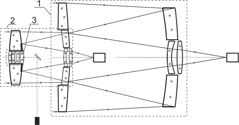
Here after we made an overview of several solutions developed by the authors and the possible use of these solutions in space applications. A distinctive feature of optical systems for space-based lenses is the requirement to minimize mass and dimensions. This condition often leads to the creation of multi-purposed optical systems, combined in common housing. Such lenses can use the optical system architectures where the certain optical surface can be a refractive element for one group of wavelengths and a mirror element for another (i.e., combining optical systems with different ray paths into the framework of one optical architecture). Fig. 1 shows the architecture of the optical system of the combined three-channel lens of the transceiver. The main purpose of the system is the creation of a secure communication channel, including the channel between the spacecrafts.
4. THE COMPACT OPTICAL SCHEMES
The process of selecting the lens architecture for space applications is associated not only with their functional application, but also with the requirements of necessary radiation resistance of the product. This requirement significantly limits the range of optical materials used. The strict weight and size limitations, as well as design requirements for dynamic loads and assembly adjustment features are necessary also. The combination of these factors often leads to significant differences with the architectures of ground-based optical systems.
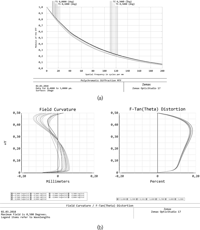
Fig. 2 shows the optical system of two mirror lenses with a three-lens corrector and an aperture diameter of 700 mm. In the basic version the angular field of view is 1°, and the corresponding linear one is 85.5 mm. The relative aperture ratio of the telescope lens is 1:7. The angular field of view can be increased without changing the basic characteristics of mirror’s part of the system by adjusting the lens corrector only. The lens is designed to operate in a wide spectral range - from 0.4 to 3 microns, which allows user to solve a wide range of problems of the Earth’s remote sensing. Fig. 3(a) shows the graph of the polychromatic modulation transfer function (PMTF) of this system. It illustrates the high, diffraction-limited image quality for all wavelengths and across the entire field of view. The field curvature and distortion plots (Fig. 3b) show the high quality correction of the corresponding aberrations. As a rule it does not require for further improvements. If necessary, the distortion can be reduced by the order of magnitude, but a significant complication of the optical surface profiles will be required.
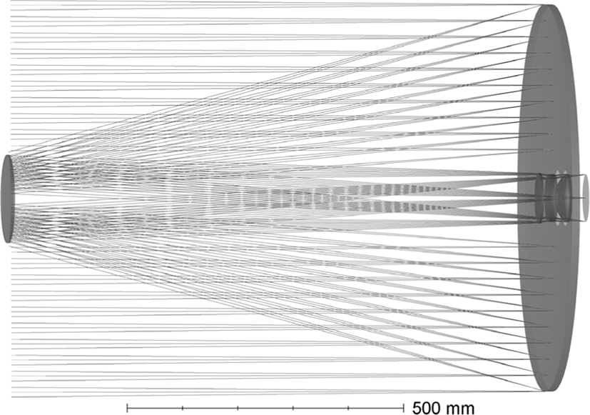
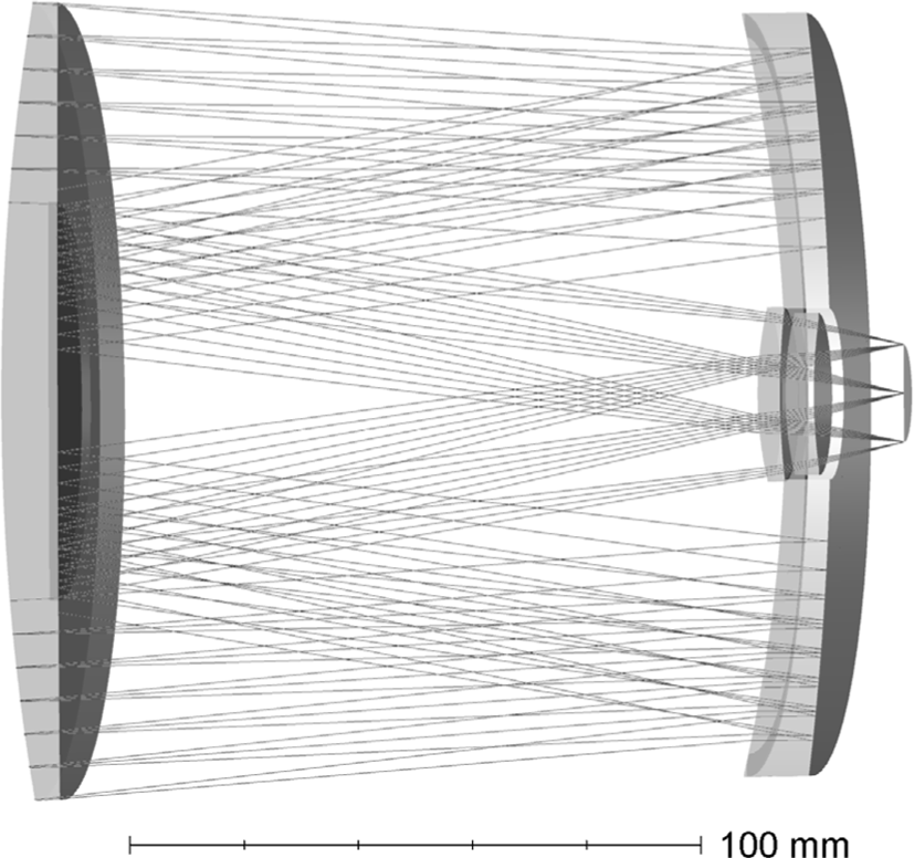
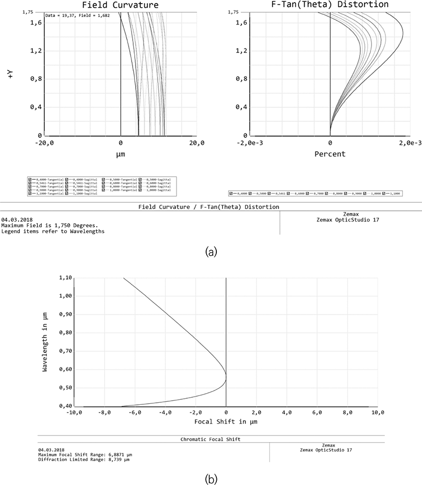
To create the small-sized lenses it is possible to construct the mirror-lens optical systems with refractive components comparable in diameter to the main aperture of the system. Taking into account the necessity of minimizing the total weight of the product, the number of such components should be as small as possible. The example is Fig. 4, where we demonstrate the compact high-aperture (1:2) mirror-lens system with an extended spectral range (0.4 – 3 μm) and a field of view of about 4 degrees. This optical system is made of one material and possesses not only diffractive image quality over the entire field, but also an ultralow value of distortion as it is shown in Fig. 5a, and chromatism (Fig. 5b). The relative apertures of similar lenses in Fig. 4 can reach 1:1, however, for systems with apertures of the order of 1:4 – 1:5, it is possible to find better solutions (depending on the special requirements, especially in terms of the angular field of view and spectral range).
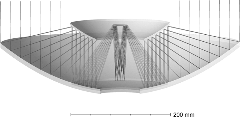
In some cases, in order to increase the resolution, the telescope lens may have several apertures. The example is shown in Fig. 6. The figure shows the compact system with an embedded ring aperture, which can be transformed by eliminating the non-used fractions of a given ray path. In the considered case with two apertures, the lens is actually an interferometer. It contains two entrance apertures and the mirror’s system. Due to multiple reflections it is quite compact in its class and provides an angular resolution of 0.3 angular seconds at 546 nm, with aperture diameters of 140 mm each. The figure does not show lens corrector and some auxiliary components to ensure multispectrality. The aperture ratio of such systems is usually near 1:15 and cannot be too high due to the construction difficulties and due to the availability of better solutions for higher aperture ratio systems.
Let us discuss the systems designed not only for visible and near infrared wavelength range, but also for mid-infrared range (for example, 8 - 14 microns). Due to a significant restriction on the choice of optical materials used, the requirement of radiation resistance, as well as due to high requirements both in image quality and aperture ratio, the range of optimal solutions for lens architectures is significantly narrowed. Both lens, mirror-lens, and purely mirror systems can be used. The example of lens system with high aperture ratio is shown in Fig. 7. The diameter is 140 mm, the aperture ratio is 1:1.4, the field of view is 6° (linear field of view is 20.6 mm). The plots of the PMTF (Fig. 8a), field curvature and distortion (Fig. 8b), and longitudinal chromatic aberration (Fig. 8c) show not only the diffraction quality of the image over the entire field (Strehl ratio is over 0.9), but also an ultralow distortion. Note, that asperical surfaces are not used in this lens, and the distorsion is less than 0.025 percent.
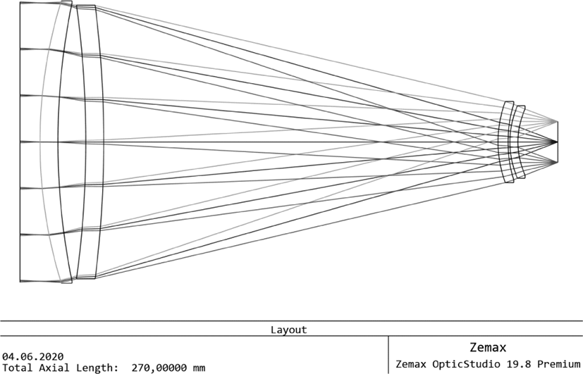
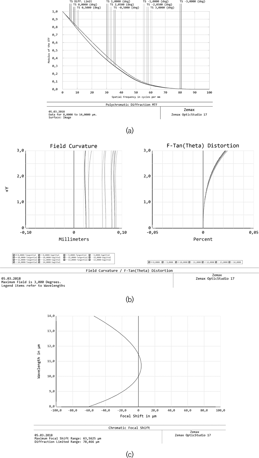
The next lens is shown in Fig. 9. The basic features of this system is similar to previous lens (Fig. 7), but of a different, compact mirror-lens design is used. It allowed the creation of more compact and low weight lens with even better aberration’s correction (see Fig. 10a, 10b). The Strehl number exceeds 0.99 over the entire field of view, the chromaticity is lower by two orders of magnitude. Nevertheless, the presence of a high (25% by area) central shielding should be taken into discussed. The comparison of Figs 8a and 10a allows the visual estimation of the influence of central shielding on the contrast of resulted image. So, for example, for a spatial frequency of 20 lines/mm, the lens, shown in Fig. 7, gives an image with a contrast twice as large as the mirror-lens lens of Fig. 9.
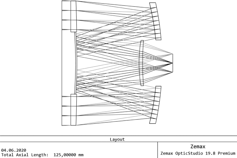
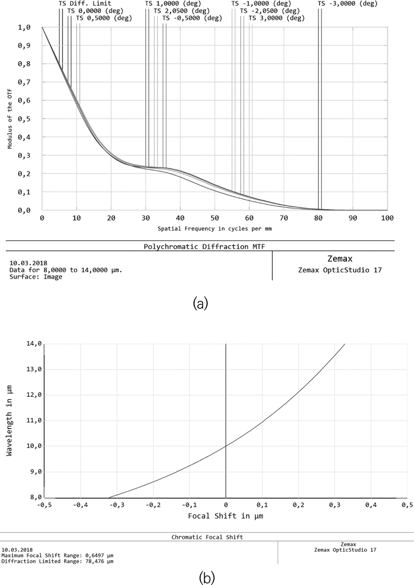
Note that the focal length and aperture ratio of these lenses are similar. However, the angular resolution of the second lens (Fig. 9) slightly exceeds the angular resolution of the first one (Fig. 7). Also, the distortion of mirror-lens system is significantly lower.
It is possible to construct compact optical systems which preserve the overall system architecture similar that of Fig. 2. Such systems are often needed in the visible and near ultraviolet range. The aperture ratios can be of the order of 1:10 or less. An example of such a system with an aperture diameter of 140 mm, spectral range from 0.4 to 2 or even 3 microns, and a aperture ratio of 1:10 is illustrated in Fig. 11. The angular field of view is 0.7°, it can be increased twice by modification of the lens corrector.
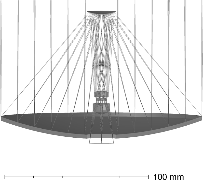
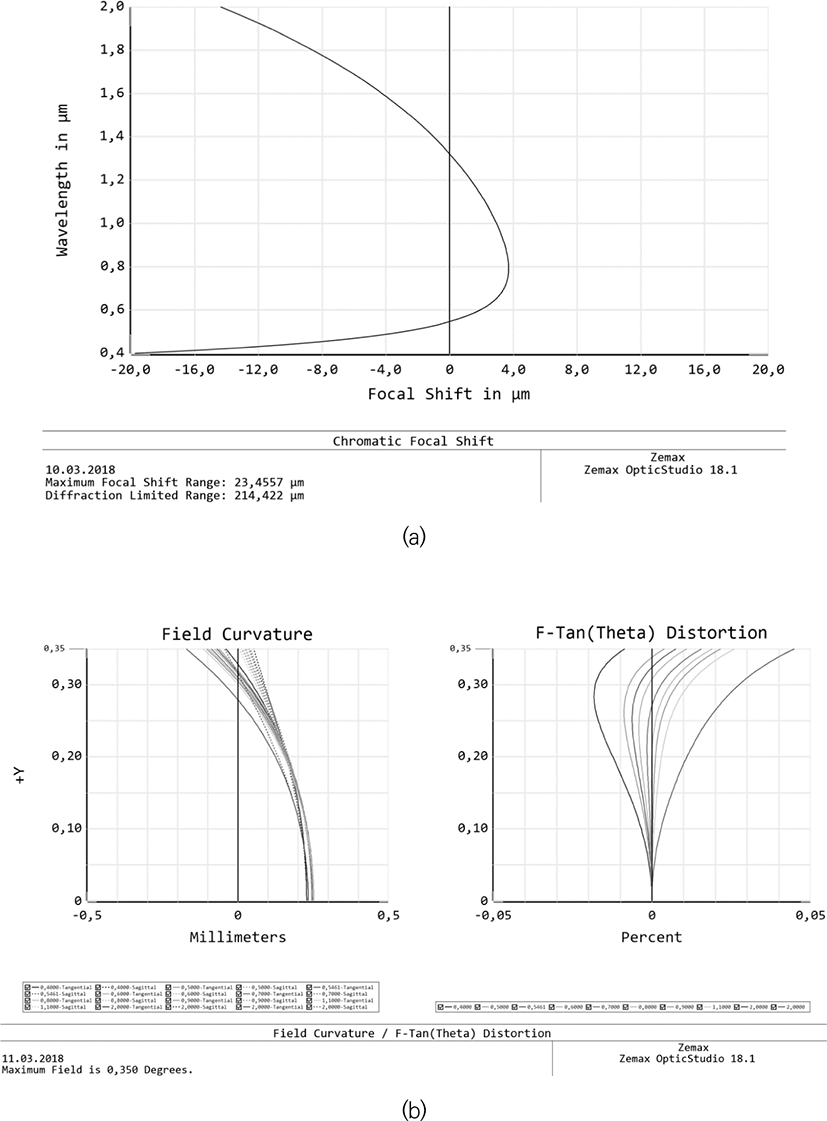
The size of this lens along the optical axe is only 90 mm, and in combination with a small-sized lens corrector, the total lens mass is negligible. Note that the reduction of lens size to 90 mm required the use of three-lens corrector with more complex configuration and the introduction of sixth-order aspherical surfaces (second-order aspherical surfaces were used in the previous scheme). Despite the complex ray path in the corrector, the chromatism of the system is small and does not affect the image quality (Fig. 12a). the distortion is also close to zero, as it is illustrated in Fig. 12b.
In some cases, when, for example, the requirements are the wide spectral range, the absence of spurious glare, and the operating under high radiation it is necessary to use of complex multi-mirror lenses, including the lenses with high values of aperture ratio and field of view. More complicated schemes usually require an integrated approach in optimization to satisfy all three of the above conditions. For this case of simple opti-mization methods used in various commercial programs are not sufficient.
That is why we developed a computer program designed for this special problem. For complex lenses, for example the lenses with variable focal length and wide-angle, such programs are compiled individually, due to the lack of universal requirements for image quality. The task is usually solved by a semi-analytical method. At the initial stage, various simplex methods (the methods without the use of derivatives) can be used to achieve a local optimum solution. The separation of different order aberrations is not done in the classical methods. Instead, the optimization function is defined so that the number of equations for its exact description is finite.
There is also no separation into axial and off-axis aberrations, since the solution of the problem only for axial aberrations is insufficient. This is especially true for systems where the uniform image quality across the entire field is required. The final part of calculations can be made with the use of usual commercial programs. Moreover, one of the criteria for the correctness of the obtained solution will be the similarity of results obtained by different programs (within the specified evaluation function) and by different optimization algorithms.
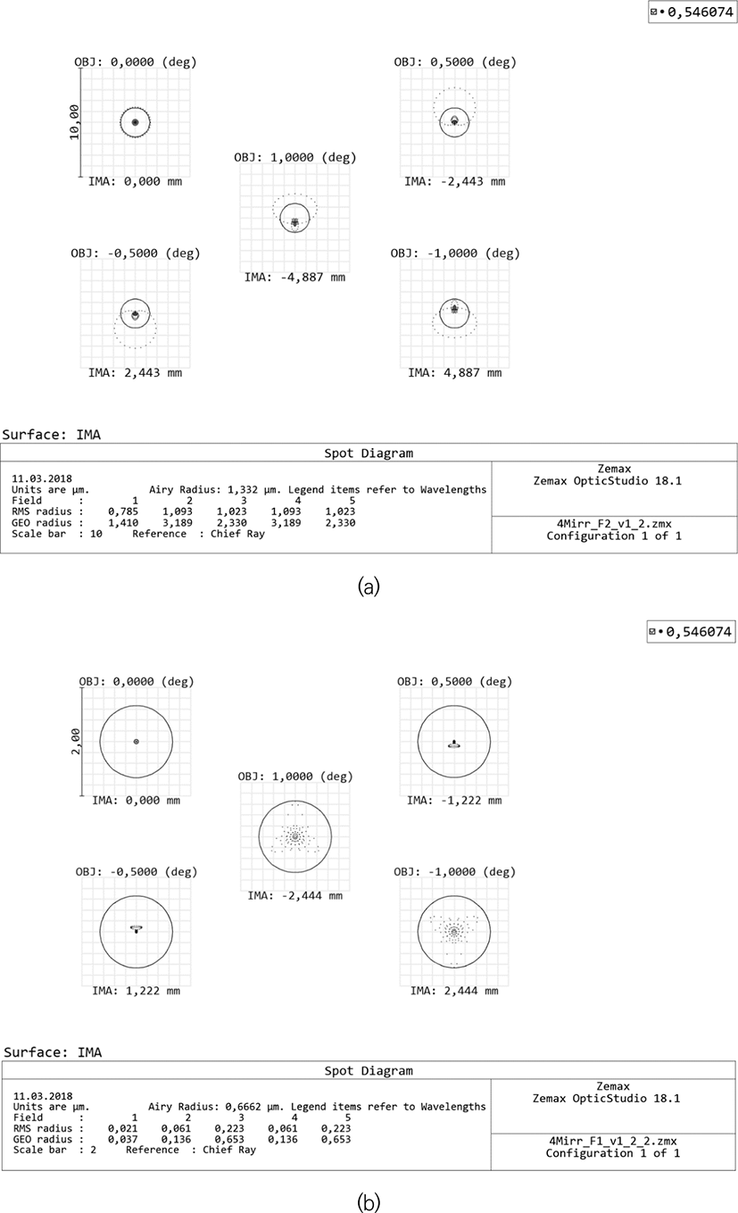
Fig. 13a and 13b show, respectively, the optical systems of high (1:2) and super high (1:1) aperture ratio four-mirror lenses developed by the author in 1987. Lenses with similar characteristics were presented for the first time [9]. In this case, the diameter of the aperture is 140 mm and the angular field of view is 2°. The central shielding of the system does not exceed 10% in area, which minimizes its negative contribution to image contrast. The scatter plots in Fig. 14a show a high and uniform diffraction limited image quality over the entire field. The lens is free of all monochromatic aberrations (the Strehl ratio at a wavelength of 546 nm exceeds 0.98 over the entire field), including distortion, the ultra-low value of which is less than 0.001 percent.
The scatter plots of Fig. 14a were calculated for the optical system of Fig. 13a with second-order surfaces only. If necessary (for example, to scale the system to a larger diameter or to increase the aperture ratio), it is possible to improve the image quality by introducing the higher-order aspherical surfaces.
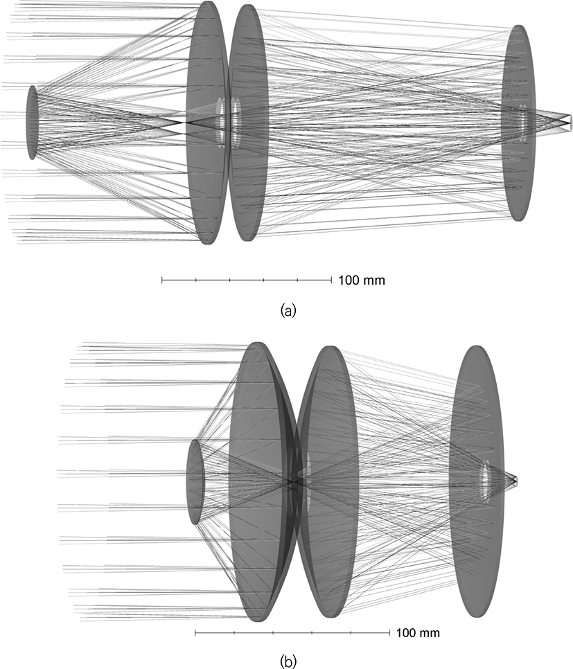
So for example a similar to Fig. 13a, a four-mirror lens with a relative aperture of 1:1 has a central shielding of only about 10% of the area and also a similar ultra-low distortion value. The image quality is also much better, as it is illustrated by the scatter plot in Fig. 14b. The presented four-mirror telescope lenses, can be developed to correct all monochromatic aberrations. As a result these systems can be easily recalculated to significantly higher input aperture values, say to the scales of 1 meter or more.
To reduce the optical system weight and production cost, it is possible to reduce the diameters of the last two mirrors several times, which is extremely desirable for the practical use of such lenses with an input aperture diameter of 300 mm or more. Such an architecture of the optical system is also advantageous for constructing the combined multispectral optical systems with high degree of compactness, low weight, and resis-tance to high accelerations.
All the results presented in this paper are not intended to predict the development of any architecture of the optical system depending on the initial data, although this possibility partially exists. Any changes in the initial data for calculating the optical systems can change not only the basic architecture of the output systems (the number of lenses, mirrors, their location, etc.), but also affect even the possibility of creating the acceptable solutions in the frames of required dimensions.
5. THE ARCHITECTURE OF ON-BOARD COMPUTER SYSTEM
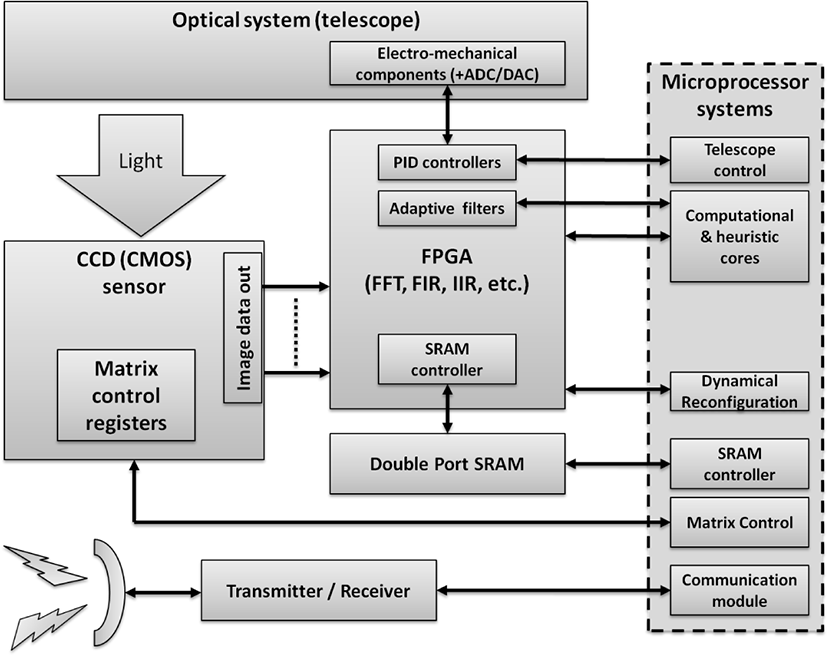
The above set of classes of space optical systems (SOS), operating in standalone mode, gives special requirements to the architecture of the on-board computer system (OBCS) used to solve various problems. Fig. 15 showed one of possible architectures of OBCS as a good example. Also, OBCS can be used for the needs of astronavigation, commu-nication, spacecraft control and other needs, beside tasks of image recognition, data processing and matrix control. The optimal computational architecture is the most critical parameter of OBSC to provide fixed-time response of the whole system without unpredictable delays and interruptions.
The OBSC architecture depends on the optical scheme of the telescope and classes of computational tasks. As a rule, OBSC architecture uses field-programmable gate array (FPGA) and special high-performance microprocessors. FPGA allows execution of primary real-time image processing tasks that require high speed information pro-cessing (for example, 2D–3D Fourier or Wavelet transforms). At the same time the OBSC microprocessors (MCU) used in more complex tasks, such as heuristic algorithms with high computational complexities, where post processing or time-critical computation executed by using FPGA parts which then will be used as an input of MCU.
FPGA ability to dynamically reconfiguration for the short time makes it strictly desirable to compare with the classical architecture with MCU only. In adaptive filtering tasks, the system response time is important, which makes such a scheme a good alternative to classical architectures. In systems where the cost, power, performance and reliability are critical such systems are good alternatives to classical architectures. Using two port synchronous memory is more preferable than error correction techniques for dram memories.
Design and manufacture of radiation-resistant computing devices requires a special approach and technologies, as well as special protection of operating equipment. As a rule, the set of concrete solutions against radiation can be determined depending on such parameters as the type of orbit, distance from the Earth, the probability of uptime and other parameters affecting the spacecraft operation, what is not a trivial task.
All calculations were carried out using the method and software, which was developed by one of the authors, as well as the Zemax OpticStudio 17 – 19.8 Premium program.
6. CONCLUSION
The schemes considered in this paper belong to the category of optimal optical systems (the ideal solution for the discussed problem) and cannot be improved without deterioration of other characteristics. This allows (according to the author’s method) to calculate the lenses with significantly different characteristics. Only a few lenses with the most interesting optical system architectures were considered here before.
It is technically possible to build systems with a higher resolution and similar dimensions (with not circular input aperture, including asymmetric apertures). However, they can be more complex (for example, the weight limit may be violated) and the describing of these question is beyond the scope of this work. Further development of space-based lens systems is possible only in combination with the development of technologies for production of high-quality light-weight optical components, as well as registration systems and image processing hardware.


